
Last Updated: November 4, 2026
Quick Summary
Plan point-to-point wireless camera transmission by surveying the path for clear line of sight, then sizing the link at roughly double your calculated camera load. A dedicated bridge pair carries video between two fixed points, while cameras still connect by Ethernet and PoE at each end.
- Survey the path at the radios' actual mounting height before ordering any gear.
- Aim for the best signal-to-noise ratio, not just the strongest RSSI reading.
- Give both bridges static IPs on a management subnet that does not overlap camera VLANs.
- Size the wireless link at roughly double your calculated camera load for headroom.
- Run a sustained ping for at least ten minutes and keep packet loss under 1%.
Table of Contents
- What a Point-to-Point Wireless Bridge Does for Cameras
- Point-to-Point Wireless Camera Transmission Setup, Step by Step
- Reading a Point-to-Point Wireless Camera Transmission Wiring Diagram
- Wireless Bridge Range for Security Cameras: What Actually Limits It
- Bandwidth Planning: Camera Count, Resolution, and Frame Rate
- Choosing the Best Point-to-Point Wireless Camera Transmission Gear
- Testing the Link: Latency, Packet Loss, and Security Hardening
- Schedule a Site Survey and Proposal
- Frequently Asked Questions
What a Point-to-Point Wireless Bridge Does for Cameras
A point-to-point wireless bridge connects two locations with a dedicated radio link, so IP cameras at a remote site reach your recorder without a cable run between buildings. Two bridge units work as a pair: one transmits at the camera end, the other receives at the network end. According to Fastcabling's 2025 point-to-point setup guide, that two-device pattern is the standard configuration for bridging remote IP cameras across buildings.
Planning these links as network infrastructure first and radio gear second is a sound approach, because that order matters more than many guides acknowledge.
Point-to-point wireless camera transmission is the practice of sending camera video over a focused radio link between two fixed points instead of copper or fiber. It suits parking lots, gatehouses, detached garages, and outbuildings where trenching is blocked or too costly.
The link replaces only the cable between buildings. Cameras still connect by Ethernet and PoE at each end. If you want the switching and Wi-Fi design behind that link handled as one system, our networking and Wi-Fi systems service is the place to start.
Point-to-Point vs. Point-to-Multipoint
Point-to-point uses one transmitter and one receiver for a single building-to-building hop. Point-to-multipoint uses one central access point to serve several remote camera sites at once.
Choose point-to-point when you have two fixed points and need the most stable throughput. Choose point-to-multipoint when three or more remote sites share one hub, accepting that each site splits the available bandwidth. If you are still weighing wireless against other cabling options, our comparison of alternatives to traditional security camera cabling lays out the trade-offs.
Point-to-Point Wireless Camera Transmission Setup, Step by Step
Here is a typical sequence for a point-to-point wireless camera transmission setup. It works with a range of bridge, camera, and NVR brands.
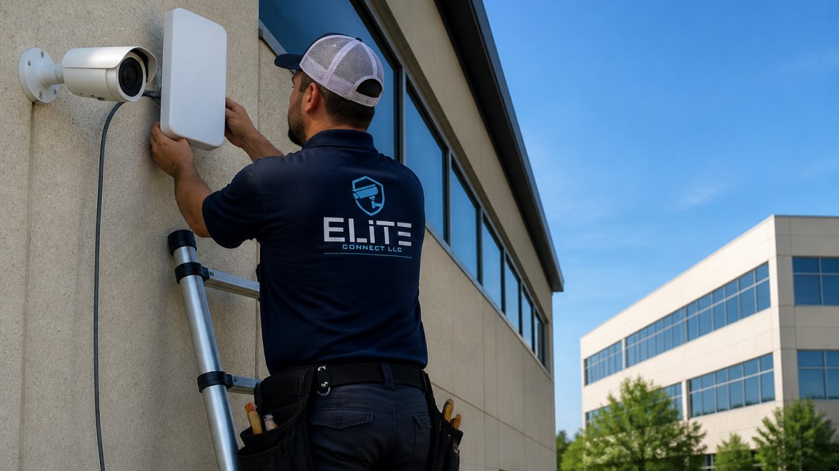
1. Survey before you buy. Walk the path between the two mounting points at the height the radios will actually sit. Confirm an unobstructed line of sight and note the first obstruction (a tree crown, a roofline, a sign).
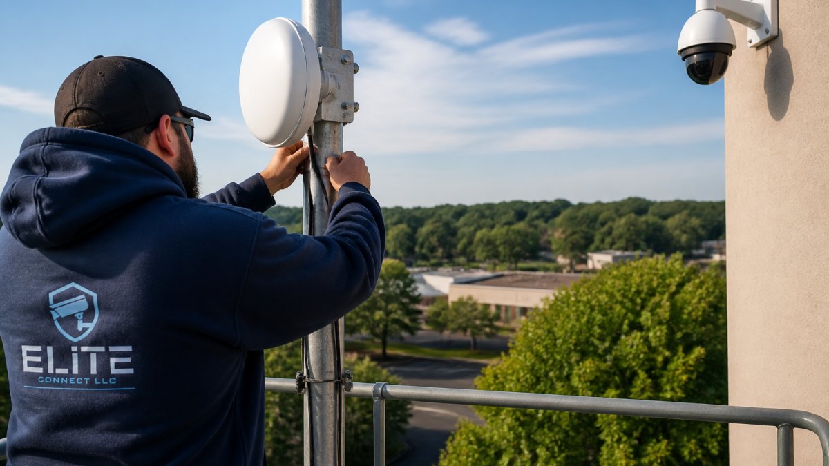
2. Mount both units rigidly. Use a mast or wall bracket rated for the radio's wind load. A rigid mount helps preserve the alignment that stable internet connectivity depends on, especially when a live event leaves little room for a dropped link.
3. Aim using the radio's own tools. Many outdoor bridges ship with an alignment mode that reports received signal strength (RSSI) and signal-to-noise ratio (SNR) in real time.
4. Run Ethernet from each bridge to its local equipment. Use Cat6 for the drop from the outdoor unit to the indoor PoE injector or PoE switch.
5. Put both bridges on your own subnet with static addresses. Give the transmitter and receiver fixed IPs on a management subnet that does not overlap your camera or office VLAN.
6. Configure one unit as transmitter and one as receiver. Set both to the same channel and channel width, and set the transmitter as the master or access-point side and the receiver as the client or station side, depending on the vendor's terminology.
7. Connect cameras at the remote side and confirm link lights. Plug the remote cameras into the remote-side PoE switch, then confirm the bridge's Ethernet and wireless link lights are solid.
**8.
9. Run a throughput and stability test and log the results. Push a sustained load equal to your planned camera bitrate for at least ten minutes and record throughput, latency, and packet loss.
Power, Grounding, and Surge Protection
Power and grounding are where cheap installs fail. Most outdoor bridges run on PoE, so the injector or PoE switch must sit indoors or in a rated enclosure. Ground the mast and use surge protectors on every cable that leaves a building. Low voltage wiring code rules cover the grounding standards that apply here.
Watch out: powering an outdoor bridge from an injector that sits in an unvented outdoor box invites condensation and heat failures; keep the injector indoors or in a rated enclosure with drainage.
Reading a Point-to-Point Wireless Camera Transmission Wiring Diagram
A point-to-point wireless camera transmission wiring diagram is simple once you know the four segments. Read it left to right and the flow becomes obvious.
- Camera segment: PoE camera to a PoE switch or injector at the remote site.
- Bridge segment: switch to the outdoor bridge unit over Cat6.
- Radio segment: the wireless link between the two bridge units.
- Head-end segment: receiving bridge to your NVR and central system.
Every diagram should show the PoE source, the surge protector, and the grounding point. If yours omits any of those three, the drawing is incomplete. This is the part most guides get wrong: the radio link is the easy half, and the power path is what fails.
Wireless Bridge Range for Security Cameras: What Actually Limits It
Wireless bridge range for security cameras depends on line of sight, antenna gain, channel width, and interference, not on the number printed on the box. CCTV Camera Pros describes an outdoor bridge system recording remote IP-camera video at 10 Mbps per camera across about 1,500 feet of direct line-of-sight distance.
Advertised range assumes a clean path. In practice, range shrinks with:
- Trees and foliage in the Fresnel zone
- Metal siding and reflective roofs
- Competing radios on 5 GHz or 5.8 GHz
- Long, lossy cable runs at either end
- Poor antenna alignment
The Fresnel zone is an important factor in link planning. The radio signal does not travel in a pencil-thin line; it spreads into an elliptical volume around the direct path, and that volume must be mostly clear of obstructions. As a rule of thumb, the first Fresnel zone is widest at the midpoint of the link and narrows toward each antenna. A tree crown or roofline that intrudes into even part of that zone can degrade the link far more than its visual footprint suggests. When you survey, check clearance at the midpoint, not just at the two ends, and raise a mount if the midpoint is blocked.
Channel selection and interference. On 5 GHz, choose a channel that is not already busy with neighboring radios, and prefer wider channels only when the noise floor is low. A wider channel carries more throughput but also collects more interference; on a noisy site, a narrower channel often delivers more usable camera performance. Use the bridge's spectrum or site-survey readout to see what else is transmitting before you commit to a channel.
Plan for margin, then test. Real-world distance generally varies with conditions rather than matching a single advertised figure. Size the link so your planned camera load uses roughly half of the tested throughput, then verify with a sustained load test rather than a single speed check. A link that passes a quick speed test can still drop frames under continuous multi-camera recording.
Watch out: a link that looks strong on a clear winter day can fail once foliage leafs out or a new rooftop unit is installed in the path; re-survey after seasonal changes or site construction.
Bandwidth Planning: Camera Count, Resolution, and Frame Rate
Bandwidth planning starts with a simple sum: cameras times bitrate per camera. A 4 MP camera at 15 frames per second typically needs a few Mbps, so five of them can saturate a modest link once overhead is added.
Use this planning table before you buy radios:
| Cameras | Resolution | Frame Rate | Planning Throughput |
|---|---|---|---|
| 2 | 1080p | 15 fps | ~8 Mbps |
| 4 | 4 MP | 15 fps | ~20 Mbps |
| 6 | 4 MP | 20 fps | ~35 Mbps |
| 8 | 4K | 15 fps | ~60 Mbps |
Size the wireless link at roughly double your calculated load. That headroom absorbs retries, interference, and future cameras. Record on the NVR at the remote site when bandwidth is tight, then stream only what you need.
Choosing the Best Point-to-Point Wireless Camera Transmission Gear
Matched pairs of outdoor bridge units rated for your distance, with PoE support and weatherproof enclosures, are a common choice for this kind of link. Buy both units from the same line so the radio settings match.
Common criteria to check before selecting any bridge:
- Rated throughput above your planned load
- PoE input and a weatherproof housing
- 5 GHz support with adjustable channel width
- Mounting hardware rated for wind load
- Management software with signal-strength readouts
Consumer Wi-Fi extenders share spectrum with client devices and can drop under sustained video load, so a dedicated bridge is often preferred for camera traffic.
For the camera and recorder side of the job, our CCTV and security camera services cover mounting, NVR setup, and remote viewing.
Testing the Link: Latency, Packet Loss, and Security Hardening
Test the link before you call the job done. Run a sustained ping for at least ten minutes and record latency and packet loss. Anything above 1% packet loss will show as stutter in recorded video.
Then harden the radio link:
- Change default admin credentials on both bridges
- Enable WPA2 or WPA3 encryption on the wireless link
- Disable unused services and remote management
- Put cameras on a separate VLAN from office traffic
- Keep firmware current on bridges, cameras, and NVR
Research funded by the National Science Foundation examined how wireless cameras can be located through their motion-activated network traffic. The lesson for installers is direct: encrypt the link and segment the network.
Watch out: skipping encryption on the bridge can expose your camera feed to anyone within radio range.
Schedule a Site Survey and Proposal
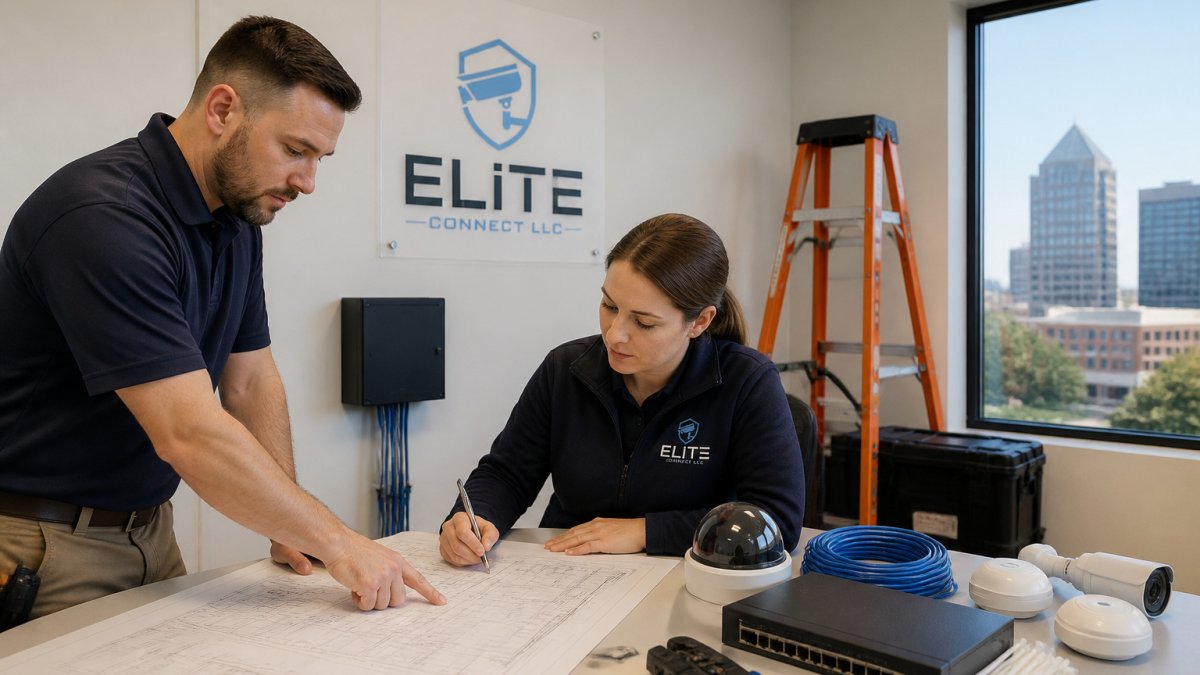
A site survey settles the questions a spec sheet cannot: real distance, real obstructions, real power locations. Surveys typically cover the path, line of sight, interference, and where PoE and grounding will land.
Elite Connect provides itemized proposals and comprehensive documentation, including test results and as-builts. If you are ready to move, book a free consultation and we will scope the link.
Frequently Asked Questions
How far can a point-to-point wireless bridge reach for security cameras?
Advertised range and usable range are different numbers. Real distance depends on several factors rather than a single spec. In practice, a clean line of sight, a clear Fresnel zone, and a 5 GHz or 5.8 GHz radio with a directional antenna matter more than the box claim. Survey the path before you commit to a distance.
How does point-to-point wireless camera transmission work?
Two bridge radios form the link. One sits at the camera location as the transmitter, and the other at the receiving end connects to your NVR or central system. Each radio connects by Ethernet to the local network, so IP and PoE cameras behave exactly as if they were cabled to the switch. The radios handle the wireless hop; everything else stays standard TCP/IP.
Can a wireless bridge transmit camera video through walls?
Not reliably. A bridge link is designed for building-to-building paths with clear outdoor line of sight. Brick, metal siding, foil-backed insulation, and dense foliage all cut signal strength and can push packet loss high enough to drop camera feeds. If a wall sits in the path, plan a mounting point that clears it, or route the link around the obstruction rather than through it.
What equipment do I need for a point-to-point camera link?
At minimum: two bridge radios with directional antennas, weatherproof mounting hardware rated for outdoor installation, shielded Ethernet cable, PoE injectors or a PoE switch, and surge protection on both ends. Add a small enclosure and grounding kit at the remote site. Bandwidth headroom matters too, so size the radios above your total camera throughput rather than at it. Elite Connect can scope the equipment needs during a site survey and provide an itemized proposal.
Point-to-point links fail at the edges: grounding, alignment, and bandwidth margin. Elite Connect LLC plans all three before a single radio goes up, backed by itemized proposals, test results, and as-built documentation. Get started with Elite Connect LLC and put your remote cameras on a link that holds.